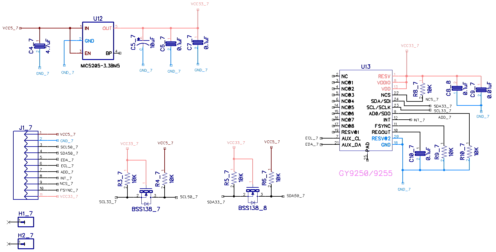
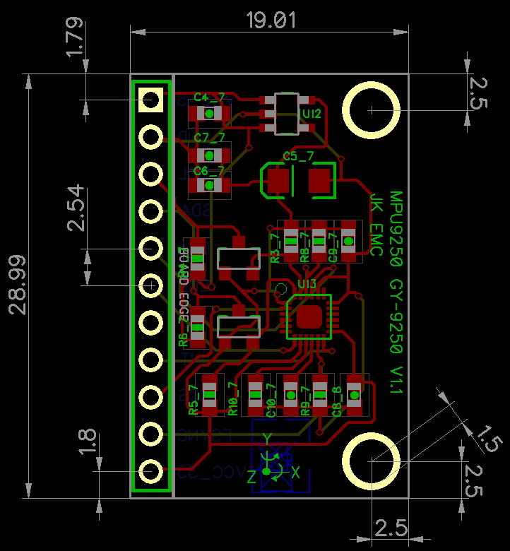
MPU9250은 MPU6050세서의 후속으로 가속도와 자이로센서, AK8963 지자기 센거가 1개의 센서에 모두 포함하고
있는 9DOF(Degrees of Freedom)
센서이다. MPU9250은 I2C (Inter Integrated Circuit) 통신 프로토콜을 통해서
데이터를 추출
할 수 있다. 모듈 내부에 전원 레률레이터를 포함하고 있어 3.3V ~ 5V 전원을 모두 사용할 수 있다.
1.1 자이로 센서
센서값 입력 범위를 ±250, ±500, ±1000,
±2000°/sec 단위로 조정이 가능하고 16bit ADC를 내장하고 있다.
1.2 가속도 센서
±2g, ±4g, ±8g, ±16g 단위로 조정이 가능하고 16bit
ADC를 내장하고 있다.
1.3 지자기 센서
3축 실리콘 모놀리식(단일 암석 사용) 회로를 사용하였다.
13bit로 값을 출력하며 각 0.3uT의 분해능, 최대 측정은
±1200uT
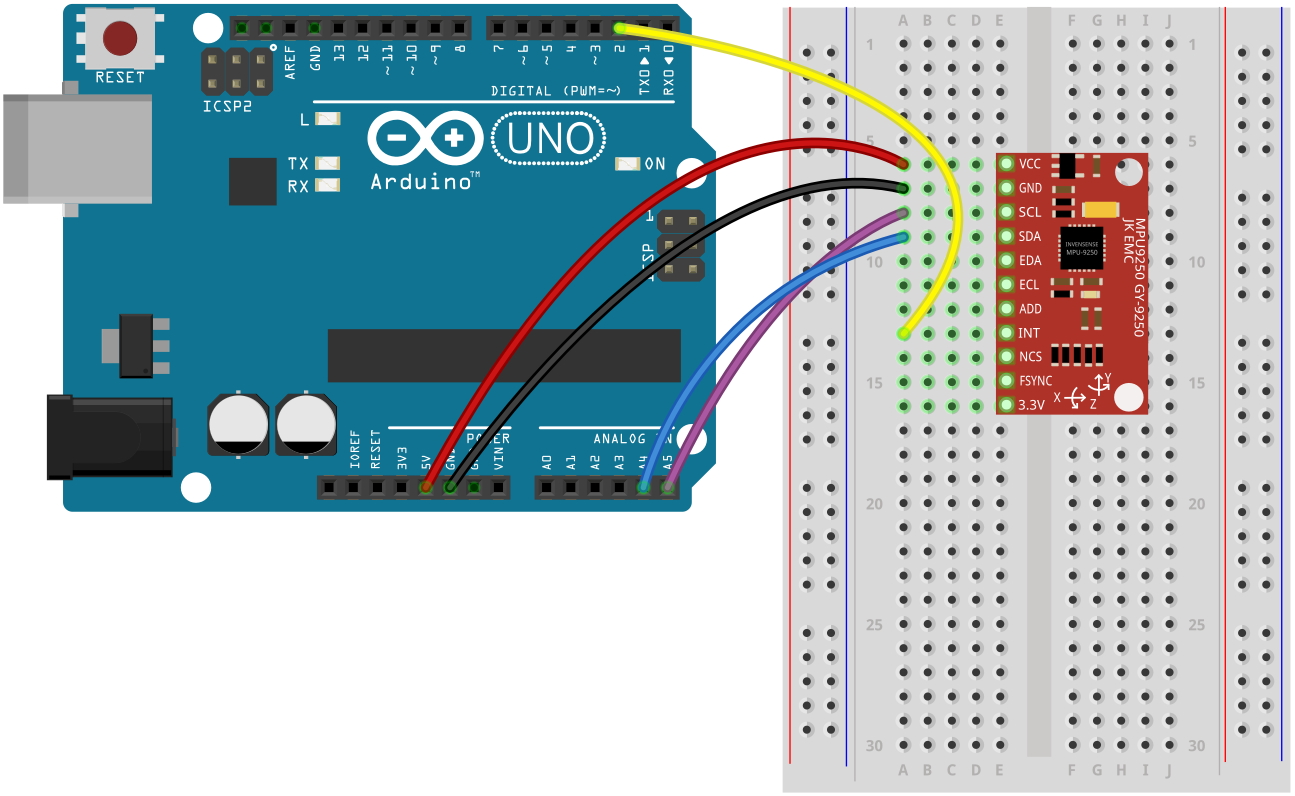
(1) 아두이노 UNO R3와 연결해서 가속도, 자이로 센터 데이터 출력 하기
이번 예제에서는 인터럽트를 사용하지 않기 때문에 INT핀을 연결할
필요는 없다. 본 제품은 내부에 회로적으로 3.3V전원
레듈레이터와 I2C 레벨쉬프터를 내장하고 있어서 5.0V와 3.3V 에서 모두 사용이 가능 하다. STM32, 라즈베리파이 등과
같이 3.3V 전원을 사용하는 프로세서에서 사용할 경우에는 VCC 대신에 3.3V 핀을 통해서 전원을 바로 연결해 주면 된다.
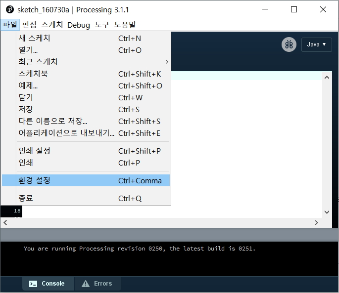
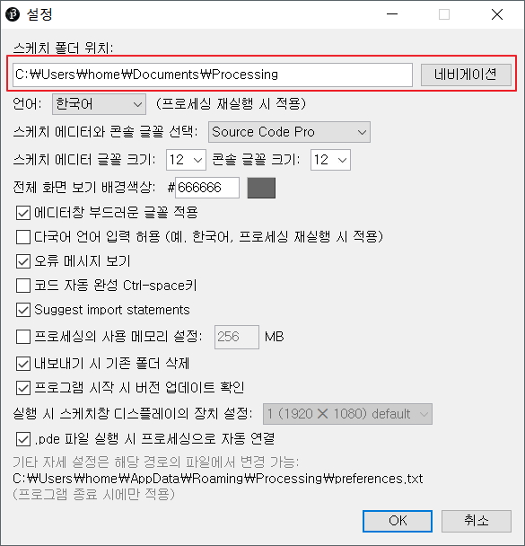
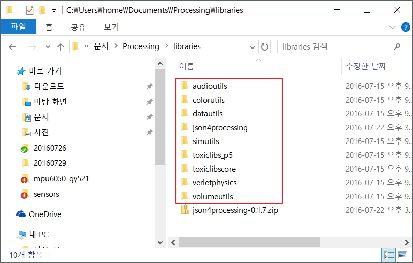
"스케치 폴더 위치/libraries" 폴더에
다운로드 받은 toxiclibs-complete-0020.zip 압축 파일을 해제해서 넣어 놓으면 된다. 라이브러리를 새로
설치하고 나면 프로세싱 프로그램을 종료하고 다시 시작해야 적용이 완료 된다.
toxiclib 라이브러리가 모두 설치된
화면이다. 위 그림에서 json4processing 라이브러리는 본 예제를 실행 하는데는 필요하지 않다. 여기 까지 프로세싱
코드 실행을 위한 모든 준비가 되었다. 프로세싱코드는 MPUP9250 모듈에서 출력하는 데이터를 시리얼(RS232) 통신을
통해서 입력을 받아 데이터를 처리 하도록 되어 있다. 이제 아두이노와 MPU9250 모듈을 이용해서 프로세싱에서 처리 하기 위한
데이터 출력을 해보자.
3.2
아두이노 UNO R3 배선도
이전 예제 에서는 MPU9250의 INT 핀을 사용하지 않았는데 이번 예제에서는 아두이노에서
인터럽트를 사용하고 있기 때문에 INT핀을 아두이노의 D2핀에 연결을 해주었다. 나머지 배선도는 이전 예제와 동일하다.
3.3
아두이노 스케치 코드
(1) 아두이노 프로세싱 코드
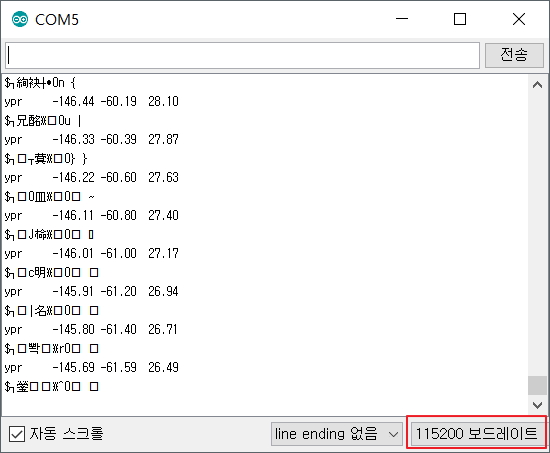
프로세싱 코드에서 한가지 주의 해야할 사항은 처리 속도를 빠르게 하기 위해서 시리통 통신의 속도를 115200bps 로 설정을
하였다. 그렇기 때문에 아두이노의 시리얼 모니터창에서도 동일한 통신속도를 맞추어 주어야 한다.
// I2C device class (I2Cdev) demonstration Arduino sketch for MPU9250 class using DMP (MotionApps v2.0) // 6/21/2012 by Jeff Rowberg <jeff@rowberg.net> // Updates should (hopefully) always be available at https://github.com/jrowberg/i2cdevlib // // Changelog: // 2013-05-08 - added seamless Fastwire support // - added note about gyro calibration // 2012-06-21 - added note about Arduino 1.0.1 + Leonardo compatibility error // 2012-06-20 - improved FIFO overflow handling and simplified read process // 2012-06-19 - completely rearranged DMP initialization code and simplification // 2012-06-13 - pull gyro and accel data from FIFO packet instead of reading directly // 2012-06-09 - fix broken FIFO read sequence and change interrupt detection to RISING // 2012-06-05 - add gravity-compensated initial reference frame acceleration output // - add 3D math helper file to DMP6 example sketch // - add Euler output and Yaw/Pitch/Roll output formats // 2012-06-04 - remove accel offset clearing for better results (thanks Sungon Lee) // 2012-06-01 - fixed gyro sensitivity to be 2000 deg/sec instead of 250 // 2012-05-30 - basic DMP initialization working /* ============================================ I2Cdev device library code is placed under the MIT license Copyright (c) 2012 Jeff Rowberg Permission is hereby granted, free of charge, to any person obtaining a copy of this software and associated documentation files (the "Software"), to deal in the Software without restriction, including without limitation the rights to use, copy, modify, merge, publish, distribute, sublicense, and/or sell copies of the Software, and to permit persons to whom the Software is furnished to do so, subject to the following conditions: The above copyright notice and this permission notice shall be included in all copies or substantial portions of the Software. THE SOFTWARE IS PROVIDED "AS IS", WITHOUT WARRANTY OF ANY KIND, EXPRESS OR IMPLIED, INCLUDING BUT NOT LIMITED TO THE WARRANTIES OF MERCHANTABILITY, FITNESS FOR A PARTICULAR PURPOSE AND NONINFRINGEMENT. IN NO EVENT SHALL THE AUTHORS OR COPYRIGHT HOLDERS BE LIABLE FOR ANY CLAIM, DAMAGES OR OTHER LIABILITY, WHETHER IN AN ACTION OF CONTRACT, TORT OR OTHERWISE, ARISING FROM, OUT OF OR IN CONNECTION WITH THE SOFTWARE OR THE USE OR OTHER DEALINGS IN THE SOFTWARE. =============================================== */ // I2Cdev and MPU9250 must be installed as libraries, or else the .cpp/.h files // for both classes must be in the include path of your project #include "I2Cdev.h" #include "MPU9250_9Axis_MotionApps41.h" //#include "MPU9250.h" // not necessary if using MotionApps include file // Arduino Wire library is required if I2Cdev I2CDEV_ARDUINO_WIRE implementation // is used in I2Cdev.h #if I2CDEV_IMPLEMENTATION == I2CDEV_ARDUINO_WIRE #include "Wire.h" #endif // class default I2C address is 0x68 // specific I2C addresses may be passed as a parameter here // AD0 low = 0x68 (default for SparkFun breakout and InvenSense evaluation board) // AD0 high = 0x69 MPU9250 mpu; //MPU9250 mpu(0x69); // <-- use for AD0 high /* ========================================================================= NOTE: In addition to connection 3.3v, GND, SDA, and SCL, this sketch depends on the MPU-9250's INT pin being connected to the Arduino's external interrupt #0 pin. On the Arduino Uno and Mega 2560, this is digital I/O pin 2. * ========================================================================= */ /* ========================================================================= NOTE: Arduino v1.0.1 with the Leonardo board generates a compile error when using Serial.write(buf, len). The Teapot output uses this method. The solution requires a modification to the Arduino USBAPI.h file, which is fortunately simple, but annoying. This will be fixed in the next IDE release. For more info, see these links: http://arduino.cc/forum/index.php/topic,109987.0.html http://code.google.com/p/arduino/issues/detail?id=958 * ========================================================================= */ // uncomment "OUTPUT_READABLE_QUATERNION" if you want to see the actual // quaternion components in a [w, x, y, z] format (not best for parsing // on a remote host such as Processing or something though) //#define OUTPUT_READABLE_QUATERNION // uncomment "OUTPUT_READABLE_EULER" if you want to see Euler angles // (in degrees) calculated from the quaternions coming from the FIFO. // Note that Euler angles suffer from gimbal lock (for more info, see // http://en.wikipedia.org/wiki/Gimbal_lock) //#define OUTPUT_READABLE_EULER // uncomment "OUTPUT_READABLE_YAWPITCHROLL" if you want to see the yaw/ // pitch/roll angles (in degrees) calculated from the quaternions coming // from the FIFO. Note this also requires gravity vector calculations. // Also note that yaw/pitch/roll angles suffer from gimbal lock (for // more info, see: http://en.wikipedia.org/wiki/Gimbal_lock) #define OUTPUT_READABLE_YAWPITCHROLL // uncomment "OUTPUT_READABLE_REALACCEL" if you want to see acceleration // components with gravity removed. This acceleration reference frame is // not compensated for orientation, so +X is always +X according to the // sensor, just without the effects of gravity. If you want acceleration // compensated for orientation, us OUTPUT_READABLE_WORLDACCEL instead. //#define OUTPUT_READABLE_REALACCEL // uncomment "OUTPUT_READABLE_WORLDACCEL" if you want to see acceleration // components with gravity removed and adjusted for the world frame of // reference (yaw is relative to initial orientation, since no magnetometer // is present in this case). Could be quite handy in some cases. //#define OUTPUT_READABLE_WORLDACCEL // uncomment "OUTPUT_TEAPOT" if you want output that matches the // format used for the InvenSense teapot demo #define OUTPUT_TEAPOT // processing #define INTERRUPT_PIN 2 // use pin 2 on Arduino Uno & most boards #define LED_PIN 13 // (Arduino is 13, Teensy is 11, Teensy++ is 6) bool blinkState =false; // MPU control/status vars bool dmpReady =false; // set true if DMP init was successful uint8_t mpuIntStatus; // holds actual interrupt status byte from MPU uint8_t devStatus; // return status after each device operation (0 = success, !0 = error) uint16_t packetSize; // expected DMP packet size (default is 42 bytes) uint16_t fifoCount; // count of all bytes currently in FIFO uint8_t fifoBuffer[64]; // FIFO storage buffer // orientation/motion vars Quaternion q; // [w, x, y, z] quaternion container VectorInt16 aa; // [x, y, z] accel sensor measurements VectorInt16 aaReal; // [x, y, z] gravity-free accel sensor measurements VectorInt16 aaWorld; // [x, y, z] world-frame accel sensor measurements VectorFloat gravity; // [x, y, z] gravity vector float euler[3]; // [psi, theta, phi] Euler angle container float ypr[3]; // [yaw, pitch, roll] yaw/pitch/roll container and gravity vector // packet structure for InvenSense teapot demo uint8_t teapotPacket[14] = { '$', 0x02, 0,0, 0,0, 0,0, 0,0, 0x00, 0x00, '\r', '\n' }; // ================================================================ // === INTERRUPT DETECTION ROUTINE === // ================================================================ volatilebool mpuInterrupt =false; // indicates whether MPU interrupt pin has gone high voiddmpDataReady() { mpuInterrupt =true; } // ================================================================ // === INITIAL SETUP === // ================================================================ voidsetup() { // join I2C bus (I2Cdev library doesn't do this automatically) #if I2CDEV_IMPLEMENTATION == I2CDEV_ARDUINO_WIRE Wire.begin(); Wire.setClock(400000); // 400kHz I2C clock. Comment this line if having compilation difficulties #elif I2CDEV_IMPLEMENTATION == I2CDEV_BUILTIN_FASTWIRE Fastwire::setup(400, true); #endif // initialize serial communication // (115200 chosen because it is required for Teapot Demo output, but it's // really up to you depending on your project) Serial.begin(115200); while (!Serial); // wait for Leonardo enumeration, others continue immediately // NOTE: 8MHz or slower host processors, like the Teensy @ 3.3v or Ardunio // Pro Mini running at 3.3v, cannot handle this baud rate reliably due to // the baud timing being too misaligned with processor ticks. You must use // 38400 or slower in these cases, or use some kind of external separate // crystal solution for the UART timer. // initialize device Serial.println(F("Initializing I2C devices...")); mpu.initialize(); pinMode(INTERRUPT_PIN, INPUT); // verify connection Serial.println(F("Testing device connections...")); Serial.println(mpu.testConnection() ? F("MPU9250 connection successful") : F("MPU9250 connection failed")); // wait for ready //Serial.println(F("\nSend any character to begin DMP programming and demo: ")); //while (Serial.available() && Serial.read()); // empty buffer //while (!Serial.available()); // wait for data //while (Serial.available() && Serial.read()); // empty buffer again // load and configure the DMP Serial.println(F("Initializing DMP...")); devStatus = mpu.dmpInitialize(); // supply your own gyro offsets here, scaled for min sensitivity mpu.setXGyroOffset(220); mpu.setYGyroOffset(76); mpu.setZGyroOffset(-85); mpu.setZAccelOffset(1788); // 1688 factory default for my test chip // make sure it worked (returns 0 if so) if (devStatus ==0) { // turn on the DMP, now that it's ready Serial.println(F("Enabling DMP...")); mpu.setDMPEnabled(true); // enable Arduino interrupt detection Serial.println(F("Enabling interrupt detection (Arduino external interrupt 0)...")); attachInterrupt(digitalPinToInterrupt(INTERRUPT_PIN), dmpDataReady, RISING); mpuIntStatus = mpu.getIntStatus(); // set our DMP Ready flag so the main loop() function knows it's okay to use it Serial.println(F("DMP ready! Waiting for first interrupt...")); dmpReady =true; // get expected DMP packet size for later comparison packetSize = mpu.dmpGetFIFOPacketSize(); } else { // ERROR! // 1 = initial memory load failed // 2 = DMP configuration updates failed // (if it's going to break, usually the code will be 1) Serial.print(F("DMP Initialization failed (code ")); Serial.print(devStatus); Serial.println(F(")")); } // configure LED for output pinMode(LED_PIN, OUTPUT); } // ================================================================ // === MAIN PROGRAM LOOP === // ================================================================ voidloop() { // if programming failed, don't try to do anything if (!dmpReady) return; // wait for MPU interrupt or extra packet(s) available while (!mpuInterrupt && fifoCount < packetSize) { // other program behavior stuff here // . // . // . // if you are really paranoid you can frequently test in between other // stuff to see if mpuInterrupt is true, and if so, "break;" from the // while() loop to immediately process the MPU data // . // . // . } // reset interrupt flag and get INT_STATUS byte mpuInterrupt =false; mpuIntStatus = mpu.getIntStatus(); // get current FIFO count fifoCount = mpu.getFIFOCount(); // check for overflow (this should never happen unless our code is too inefficient) if ((mpuIntStatus &0x10) || fifoCount ==1024) { // reset so we can continue cleanly mpu.resetFIFO(); Serial.println(F("FIFO overflow!")); // otherwise, check for DMP data ready interrupt (this should happen frequently) } elseif (mpuIntStatus &0x02) { // wait for correct available data length, should be a VERY short wait while (fifoCount < packetSize) fifoCount = mpu.getFIFOCount(); // read a packet from FIFO mpu.getFIFOBytes(fifoBuffer, packetSize); // track FIFO count here in case there is > 1 packet available // (this lets us immediately read more without waiting for an interrupt) fifoCount -= packetSize; #ifdef OUTPUT_READABLE_QUATERNION // display quaternion values in easy matrix form: w x y z mpu.dmpGetQuaternion(&q, fifoBuffer); Serial.print("quat\t"); Serial.print(q.w); Serial.print("\t"); Serial.print(q.x); Serial.print("\t"); Serial.print(q.y); Serial.print("\t"); Serial.println(q.z); #endif #ifdef OUTPUT_READABLE_EULER // display Euler angles in degrees mpu.dmpGetQuaternion(&q, fifoBuffer); mpu.dmpGetEuler(euler, &q); Serial.print("euler\t"); Serial.print(euler[0] *180/M_PI); Serial.print("\t"); Serial.print(euler[1] *180/M_PI); Serial.print("\t"); Serial.println(euler[2] *180/M_PI); #endif #ifdef OUTPUT_READABLE_YAWPITCHROLL // display Euler angles in degrees mpu.dmpGetQuaternion(&q, fifoBuffer); mpu.dmpGetGravity(&gravity, &q); mpu.dmpGetYawPitchRoll(ypr, &q, &gravity); Serial.print("ypr\t"); Serial.print(ypr[0] *180/M_PI); Serial.print("\t"); Serial.print(ypr[1] *180/M_PI); Serial.print("\t"); Serial.println(ypr[2] *180/M_PI); #endif #ifdef OUTPUT_READABLE_REALACCEL // display real acceleration, adjusted to remove gravity mpu.dmpGetQuaternion(&q, fifoBuffer); mpu.dmpGetAccel(&aa, fifoBuffer); mpu.dmpGetGravity(&gravity, &q); mpu.dmpGetLinearAccel(&aaReal, &aa, &gravity); Serial.print("areal\t"); Serial.print(aaReal.x); Serial.print("\t"); Serial.print(aaReal.y); Serial.print("\t"); Serial.println(aaReal.z); #endif #ifdef OUTPUT_READABLE_WORLDACCEL // display initial world-frame acceleration, adjusted to remove gravity // and rotated based on known orientation from quaternion mpu.dmpGetQuaternion(&q, fifoBuffer); mpu.dmpGetAccel(&aa, fifoBuffer); mpu.dmpGetGravity(&gravity, &q); mpu.dmpGetLinearAccel(&aaReal, &aa, &gravity); mpu.dmpGetLinearAccelInWorld(&aaWorld, &aaReal, &q); Serial.print("aworld\t"); Serial.print(aaWorld.x); Serial.print("\t"); Serial.print(aaWorld.y); Serial.print("\t"); Serial.println(aaWorld.z); #endif #ifdef OUTPUT_TEAPOT // display quaternion values in InvenSense Teapot demo format: teapotPacket[2] = fifoBuffer[0]; teapotPacket[3] = fifoBuffer[1]; teapotPacket[4] = fifoBuffer[4]; teapotPacket[5] = fifoBuffer[5]; teapotPacket[6] = fifoBuffer[8]; teapotPacket[7] = fifoBuffer[9]; teapotPacket[8] = fifoBuffer[12]; teapotPacket[9] = fifoBuffer[13]; Serial.write(teapotPacket, 14); teapotPacket[11]++; // packetCount, loops at 0xFF on purpose #endif // blink LED to indicate activity blinkState =!blinkState; digitalWrite(LED_PIN, blinkState); } }
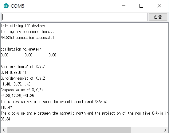
(2) 실행 결과
아두이노 시리얼 모니터창에서 반드시 보드레이트(Baudate)를 115200 으로 수정 해야 한다. 그렇지
않으면 시리얼 모니터 창에 아무런 데이터가 표시되지 않거나 잘못된 데이터가 표시될 것이다. 프로세싱 데이터를 처리하기 위한
데이터 이므로 데이터를 바로 판독하기는 어렵다. 데이터가 올바르게 표시되는것을 확인 하였다면 프로세싱에서 동일한 시리얼포트를
사용해야 하기 때문에 아두이노 시리얼 모니텅 창을 닫도록 하자.
3.4
프로세싱 코드
프로세싱 코드에서 한가지 주의 해야할 사항은 시리얼 포트를 각자의 환경에 맞추어서 수정을 해주어야 한다는 것이다.
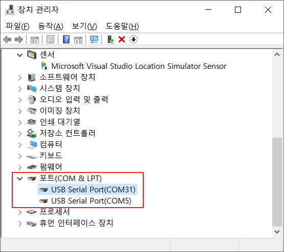
아래 프로세싱 코드에서 "[0]" 의 0이라는 숫자는 장치관리자에서 COM포트의 번호가 아니라 포트의 순서라는것에 주의 해야 한다.
위의 장치관리자 화면에서 예를 든다면 다음과 같다.
String portName = Serial.list()[0]; // --> COM31
String portName = Serial.list()[1]; // --> COM5

프로세싱 코드를 실행할때 테스트하는 PC의 COM 포트 상태에 따라서 "Serial.list()[0]" 의 숫자를 바꾸어 주어야 한다.
(1) 프로세싱 코드
// I2C device class (I2Cdev) demonstration Processing sketch for MPU6050 DMP output // 6/20/2012 by Jeff Rowberg <jeff@rowberg.net> // Updates should (hopefully) always be available at https://github.com/jrowberg/i2cdevlib // // Changelog: // 2012-06-20 - initial release /* ============================================ I2Cdev device library code is placed under the MIT license Copyright (c) 2012 Jeff Rowberg Permission is hereby granted, free of charge, to any person obtaining a copy of this software and associated documentation files (the "Software"), to deal in the Software without restriction, including without limitation the rights to use, copy, modify, merge, publish, distribute, sublicense, and/or sell copies of the Software, and to permit persons to whom the Software is furnished to do so, subject to the following conditions: The above copyright notice and this permission notice shall be included in all copies or substantial portions of the Software. THE SOFTWARE IS PROVIDED "AS IS", WITHOUT WARRANTY OF ANY KIND, EXPRESS OR IMPLIED, INCLUDING BUT NOT LIMITED TO THE WARRANTIES OF MERCHANTABILITY, FITNESS FOR A PARTICULAR PURPOSE AND NONINFRINGEMENT. IN NO EVENT SHALL THE AUTHORS OR COPYRIGHT HOLDERS BE LIABLE FOR ANY CLAIM, DAMAGES OR OTHER LIABILITY, WHETHER IN AN ACTION OF CONTRACT, TORT OR OTHERWISE, ARISING FROM, OUT OF OR IN CONNECTION WITH THE SOFTWARE OR THE USE OR OTHER DEALINGS IN THE SOFTWARE. =============================================== */ import processing.serial.*; import processing.opengl.*; import toxi.geom.*; import toxi.processing.*; // NOTE: requires ToxicLibs to be installed in order to run properly. // 1. Download from http://toxiclibs.org/downloads // 2. Extract into [userdir]/Processing/libraries // (location may be different on Mac/Linux) // 3. Run and bask in awesomeness ToxiclibsSupport gfx; Serial port; // The serial port char[] teapotPacket =newchar[14]; // InvenSense Teapot packet int serialCount =0; // current packet byte position int synced =0; int interval =0; float[] q =newfloat[4]; Quaternion quat =new Quaternion(1, 0, 0, 0); float[] gravity =newfloat[3]; float[] euler =newfloat[3]; float[] ypr =newfloat[3]; voidsetup() { // 300px square viewport using OpenGL rendering size(300, 300, OPENGL); gfx =new ToxiclibsSupport(this); // setup lights and antialiasing lights(); smooth(); // display serial port list for debugging/clarity println(Serial.list()); // get the first available port (use EITHER this OR the specific port code below) String portName = Serial.list()[0]; // get a specific serial port (use EITHER this OR the first-available code above) //String portName = "COM4"; // open the serial port port =new Serial(this, portName, 115200); // send single character to trigger DMP init/start // (expected by MPU6050_DMP6 example Arduino sketch) port.write('r'); } voiddraw() { if (millis() - interval >1000) { // resend single character to trigger DMP init/start // in case the MPU is halted/reset while applet is running port.write('r'); interval = millis(); } // black background background(0); // translate everything to the middle of the viewport pushMatrix(); translate(width /2, height /2); // 3-step rotation from yaw/pitch/roll angles (gimbal lock!) // ...and other weirdness I haven't figured out yet //rotateY(-ypr[0]); //rotateZ(-ypr[1]); //rotateX(-ypr[2]); // toxiclibs direct angle/axis rotation from quaternion (NO gimbal lock!) // (axis order [1, 3, 2] and inversion [-1, +1, +1] is a consequence of // different coordinate system orientation assumptions between Processing // and InvenSense DMP) float[] axis = quat.toAxisAngle(); rotate(axis[0], -axis[1], axis[3], axis[2]); // draw main body in red fill(255, 0, 0, 200); box(10, 10, 200); // draw front-facing tip in blue fill(0, 0, 255, 200); pushMatrix(); translate(0, 0, -120); rotateX(PI/2); drawCylinder(0, 20, 20, 8); popMatrix(); // draw wings and tail fin in green fill(0, 255, 0, 200); beginShape(TRIANGLES); vertex(-100, 2, 30); vertex(0, 2, -80); vertex(100, 2, 30); // wing top layer vertex(-100, -2, 30); vertex(0, -2, -80); vertex(100, -2, 30); // wing bottom layer vertex(-2, 0, 98); vertex(-2, -30, 98); vertex(-2, 0, 70); // tail left layer vertex( 2, 0, 98); vertex( 2, -30, 98); vertex( 2, 0, 70); // tail right layer endShape(); beginShape(QUADS); vertex(-100, 2, 30); vertex(-100, -2, 30); vertex( 0, -2, -80); vertex( 0, 2, -80); vertex( 100, 2, 30); vertex( 100, -2, 30); vertex( 0, -2, -80); vertex( 0, 2, -80); vertex(-100, 2, 30); vertex(-100, -2, 30); vertex(100, -2, 30); vertex(100, 2, 30); vertex(-2, 0, 98); vertex(2, 0, 98); vertex(2, -30, 98); vertex(-2, -30, 98); vertex(-2, 0, 98); vertex(2, 0, 98); vertex(2, 0, 70); vertex(-2, 0, 70); vertex(-2, -30, 98); vertex(2, -30, 98); vertex(2, 0, 70); vertex(-2, 0, 70); endShape(); popMatrix(); } voidserialEvent(Serial port) { interval = millis(); while (port.available() >0) { int ch = port.read(); if (synced ==0&& ch !='$') return; // initial synchronization - also used to resync/realign if needed synced =1; print ((char)ch); if ((serialCount ==1&& ch !=2) || (serialCount ==12&& ch !='\r') || (serialCount ==13&& ch !='\n')) { serialCount =0; synced =0; return; } if (serialCount >0|| ch =='$') { teapotPacket[serialCount++] = (char)ch; if (serialCount ==14) { serialCount =0; // restart packet byte position // get quaternion from data packet q[0] = ((teapotPacket[2] <<8) | teapotPacket[3]) /16384.0f; q[1] = ((teapotPacket[4] <<8) | teapotPacket[5]) /16384.0f; q[2] = ((teapotPacket[6] <<8) | teapotPacket[7]) /16384.0f; q[3] = ((teapotPacket[8] <<8) | teapotPacket[9]) /16384.0f; for (int i =0; i <4; i++) if (q[i] >=2) q[i] =-4+ q[i]; // set our toxilibs quaternion to new data quat.set(q[0], q[1], q[2], q[3]); /* // below calculations unnecessary for orientation only using toxilibs // calculate gravity vector gravity[0] = 2 * (q[1]*q[3] - q[0]*q[2]); gravity[1] = 2 * (q[0]*q[1] + q[2]*q[3]); gravity[2] = q[0]*q[0] - q[1]*q[1] - q[2]*q[2] + q[3]*q[3]; // calculate Euler angles euler[0] = atan2(2*q[1]*q[2] - 2*q[0]*q[3], 2*q[0]*q[0] + 2*q[1]*q[1] - 1); euler[1] = -asin(2*q[1]*q[3] + 2*q[0]*q[2]); euler[2] = atan2(2*q[2]*q[3] - 2*q[0]*q[1], 2*q[0]*q[0] + 2*q[3]*q[3] - 1); // calculate yaw/pitch/roll angles ypr[0] = atan2(2*q[1]*q[2] - 2*q[0]*q[3], 2*q[0]*q[0] + 2*q[1]*q[1] - 1); ypr[1] = atan(gravity[0] / sqrt(gravity[1]*gravity[1] + gravity[2]*gravity[2])); ypr[2] = atan(gravity[1] / sqrt(gravity[0]*gravity[0] + gravity[2]*gravity[2])); // output various components for debugging //println("q:\t" + round(q[0]*100.0f)/100.0f + "\t" + round(q[1]*100.0f)/100.0f + "\t" + round(q[2]*100.0f)/100.0f + "\t" + round(q[3]*100.0f)/100.0f); //println("euler:\t" + euler[0]*180.0f/PI + "\t" + euler[1]*180.0f/PI + "\t" + euler[2]*180.0f/PI); //println("ypr:\t" + ypr[0]*180.0f/PI + "\t" + ypr[1]*180.0f/PI + "\t" + ypr[2]*180.0f/PI); */ } } } } voiddrawCylinder(float topRadius, float bottomRadius, float tall, int sides) { float angle =0; float angleIncrement = TWO_PI / sides; beginShape(QUAD_STRIP); for (int i =0; i < sides +1; ++i) { vertex(topRadius*cos(angle), 0, topRadius*sin(angle)); vertex(bottomRadius*cos(angle), tall, bottomRadius*sin(angle)); angle += angleIncrement; } endShape(); // If it is not a cone, draw the circular top cap if (topRadius !=0) { angle =0; beginShape(TRIANGLE_FAN); // Center point vertex(0, 0, 0); for (int i =0; i < sides +1; i++) { vertex(topRadius * cos(angle), 0, topRadius * sin(angle)); angle += angleIncrement; } endShape(); } // If it is not a cone, draw the circular bottom cap if (bottomRadius !=0) { angle =0; beginShape(TRIANGLE_FAN); // Center point vertex(0, tall, 0); for (int i =0; i < sides +1; i++) { vertex(bottomRadius * cos(angle), tall, bottomRadius * sin(angle)); angle += angleIncrement; } endShape(); } }