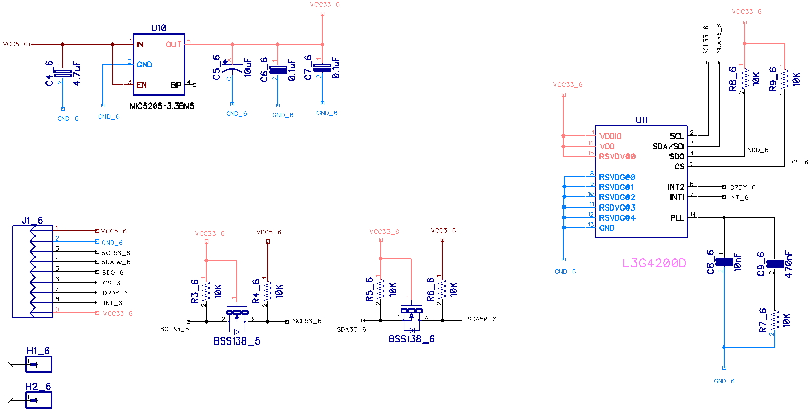
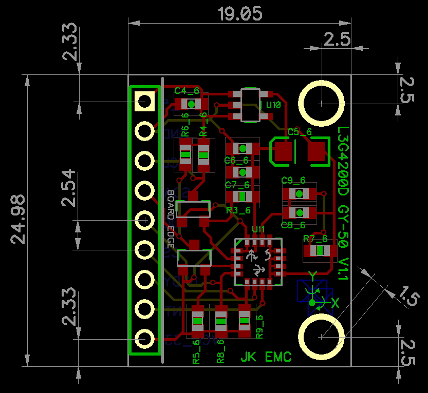
L3G4200D은
MEMS(Micro Electro Mechanical Systems) 기반의 3축 자이로 센서이다. L3G4200D는 I2C
(Inter Integrated Circuit)와 SPI 통신 프로토콜을 통해서
데이터를 추출
할 수 있다. 본 제품은 I2C 통신 인터페이스를 사용하도록 제작이 되었다. 대역폭과 속도 조절을 사용자가 프로그램 할 수
있고, 게임및 가상 현실 입력장치, GPS, 네비케이션, 로봇
시스템등에 유용하다.
// I2C device class (I2Cdev) demonstration Arduino sketch for L3G4200D class // 7/31/2013 by Jonathan Arnett <j3rn@j3rn.com> // Updates should (hopefully) always be available at https://github.com/jrowberg/i2cdevlib // // Changelog: // 2011-07-31 - initial release /* ============================================ I2Cdev device library code is placed under the MIT license Copyright (c) 2011 Jonathan Arnett, Jeff Rowberg Permission is hereby granted, free of charge, to any person obtaining a copy of this software and associated documentation files (the "Software"), to deal in the Software without restriction, including without limitation the rights to use, copy, modify, merge, publish, distribute, sublicense, and/or sell copies of the Software, and to permit persons to whom the Software is furnished to do so, subject to the following conditions: The above copyright notice and this permission notice shall be included in all copies or substantial portions of the Software. THE SOFTWARE IS PROVIDED "AS IS", WITHOUT WARRANTY OF ANY KIND, EXPRESS OR IMPLIED, INCLUDING BUT NOT LIMITED TO THE WARRANTIES OF MERCHANTABILITY, FITNESS FOR A PARTICULAR PURPOSE AND NONINFRINGEMENT. IN NO EVENT SHALL THE AUTHORS OR COPYRIGHT HOLDERS BE LIABLE FOR ANY CLAIM, DAMAGES OR OTHER LIABILITY, WHETHER IN AN ACTION OF CONTRACT, TORT OR OTHERWISE, ARISING FROM, OUT OF OR IN CONNECTION WITH THE SOFTWARE OR THE USE OR OTHER DEALINGS IN THE SOFTWARE. =============================================== */ // Arduino Wire library is required if I2Cdev I2CDEV_ARDUINO_WIRE implementation // is used in I2Cdev.h #include <Wire.h> // I2Cdev and L3G4200D must be installed as libraries, or else the .cpp/.h files // for both classes must be in the include path of your project #include "I2Cdev.h" #include "L3G4200D.h" // default address is 105 // specific I2C address may be passed here L3G4200D gyro; int16_t avx, avy, avz; #define LED_PIN 13 // (Arduino is 13, Teensy is 6) bool blinkState =false; voidsetup() { // join I2C bus (I2Cdev library doesn't do this automatically) Wire.begin(); // initialize serial communication // (38400 chosen because it works as well at 8MHz as it does at 16MHz, but // it's really up to you depending on your project) Serial.begin(9600); // initialize device Serial.println("Initializing I2C devices..."); gyro.initialize(); // verify connection Serial.println("Testing device connections..."); Serial.println(gyro.testConnection() ?"L3G4200D connection successful":"L3G4200D connection failed"); // configure LED for output pinMode(LED_PIN, OUTPUT); // data seems to be best when full scale is 2000 gyro.setFullScale(2000); } voidloop() { // read raw angular velocity measurements from device gyro.getAngularVelocity(&avx, &avy, &avz); Serial.print("angular velocity:\t"); Serial.print(avx); Serial.print("\t"); Serial.print(avy); Serial.print("\t"); Serial.println(avz); // blink LED to indicate activity blinkState =!blinkState; digitalWrite(LED_PIN, blinkState); delay(1000); }
L3G4200D의 I2C Slave Address는 기본적으로 0x69이다.
#define L3G4200D_ADDRESS 0x69
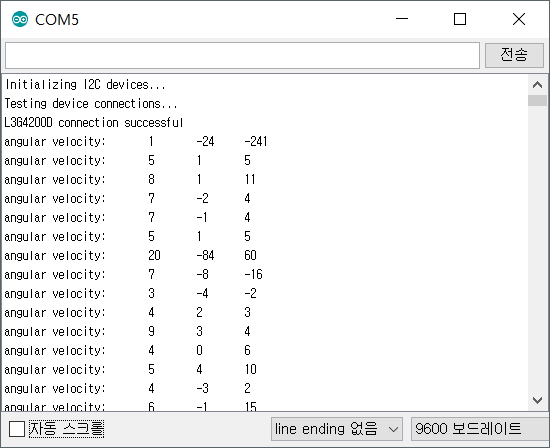
(2) 실행 결과
L3G4200D의 I2C 통신 상태를 검사하고 자이로 센서의 X, Y, Z 축의 값을 반복해서 보여준다.
(1) 프로세싱 설치 -
프로세싱 개발환경 설치 하기(새창)
프로세싱코드는 L3G4200D 모듈에서 출력하는 데이터를 시리얼(RS232) 통신을
통해서 입력을 받아 데이터를 처리 하도록 되어 있다. 이제 아두이노와 L3G4200D 모듈을 이용해서 프로세싱에서 처리 하기
위한
데이터 출력을 해보자.
3.2
아두이노 UNO R3 배선도
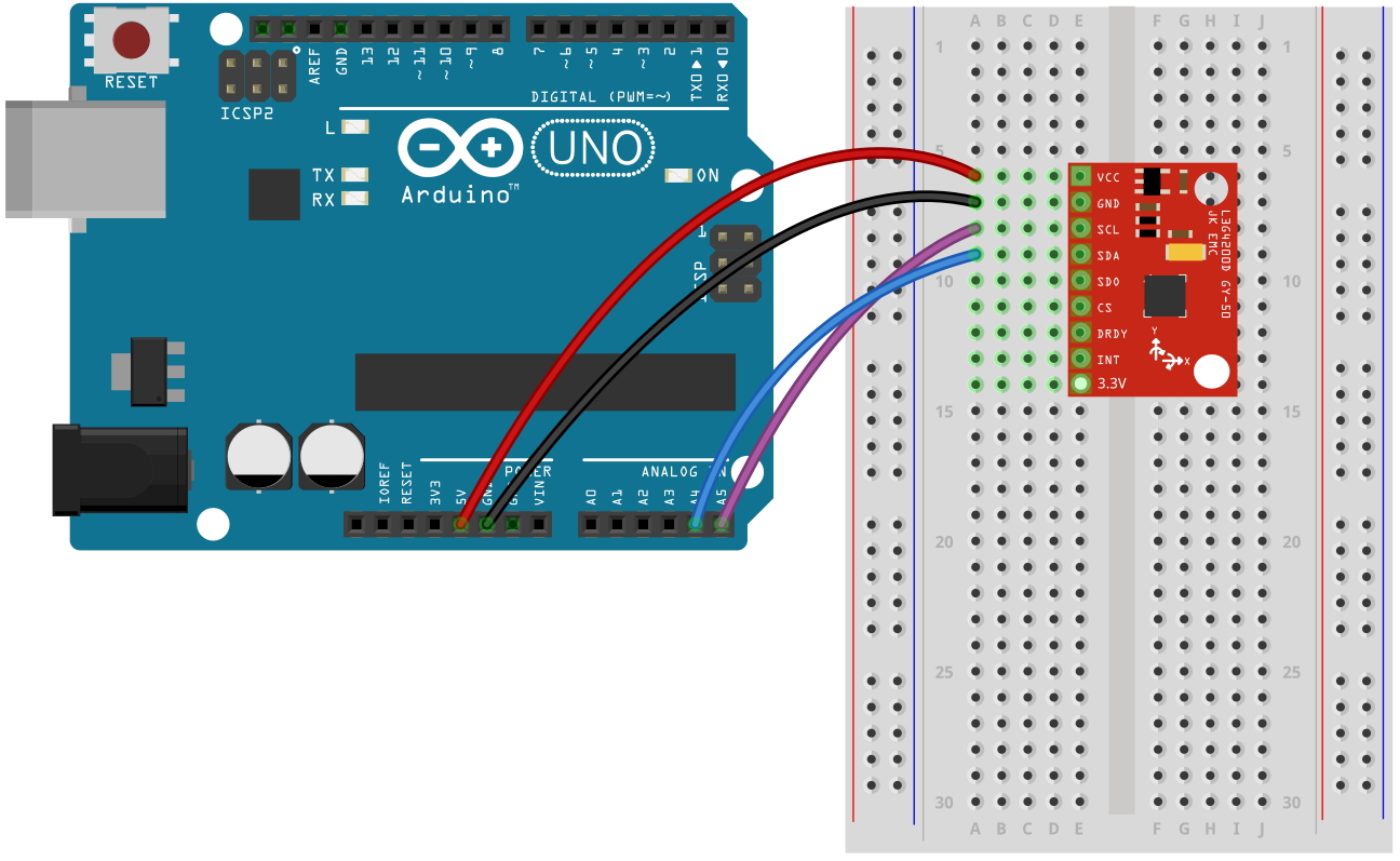
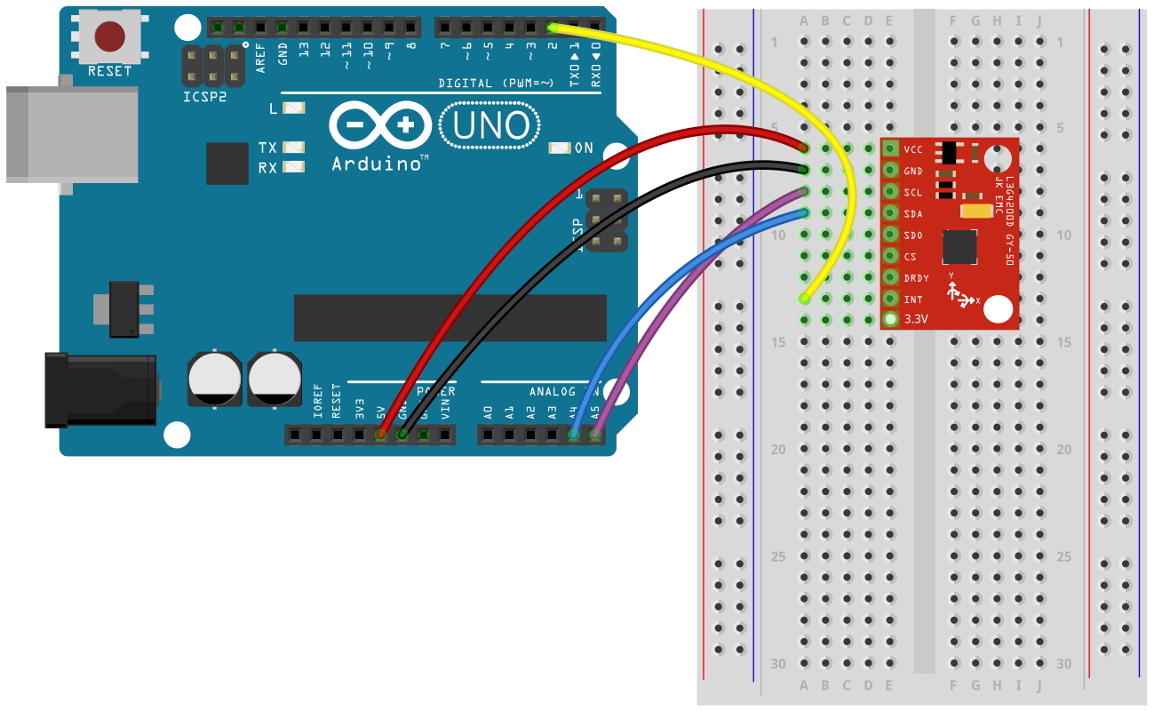
이전 예제 에서는 MPU6050의 INT 핀을 사용하지 않았는데 이번 예제에서는 아두이노에서
인터럽트를 사용하고 있기 때문에 INT핀을 아두이노의 D2핀에 연결을 해주었다. 나머지 배선도는 이전 예제와 동일하다.
3.3
아두이노 스케치 코드
(1) 아두이노 프로세싱 코드
프로세싱 코드에서 한가지 주의 해야할 사항은 시리통 통신의 속도를 9600bps 로 설정을
하였다. 그렇기 때문에 아두이노의 시리얼 모니터창에서도 동일한 통신속도를 맞추어 주어야 한다.
#include <Wire.h> #define CTRL_REG1 0x20 #define CTRL_REG2 0x21 #define CTRL_REG3 0x22 #define CTRL_REG4 0x23 #define CTRL_REG5 0x24 // I2C address of the L3G4200D. // Use I2C scanner to find this value! int L3G4200D_Address =0x69; // Can fine-tune this if you need to float DPS_MULT =0.0000085; // Delta angles (raw input from gyro) int x =0; int y =0; int z =0; // Actual angles float angX =0; float angY =0; float angZ =0; // Previous angles for calculation float p_angX =0; float p_angY =0; float p_angZ =0; // Calibration values int gyroLowX =0; int gyroLowY =0; int gyroLowZ =0; int gyroHighX =0; int gyroHighY =0; int gyroHighZ =0; // Used for calculating delta time unsignedlong pastMicros =0; voidsetup() { Wire.begin(); Serial.begin(9600); Serial.println("Starting up L3G4200D"); setupL3G4200D(250); // Configure L3G4200 - 250, 500 or 2000 deg/sec delay(1000); // wait for the sensor to be ready calibrate(); attachInterrupt(0, updateAngle, RISING); pastMicros = micros(); } voidloop() { getGyroValues(); // Calculate delta time float dt; if(micros() > pastMicros) //micros() overflows every ~70 minutes dt = (float) (micros()-pastMicros)/1000000.0; else dt = (float) ((4294967295-pastMicros)+micros())/1000000.0; // Calculate angles if(x >= gyroHighX || x <= gyroLowX) { angX += ((p_angX + (x * DPS_MULT))/2) * dt; p_angX = x * DPS_MULT; } else { p_angX =0; } if(y >= gyroHighY || y <= gyroLowY) { angY += ((p_angY + (y * DPS_MULT))/2) * dt; p_angY = y * DPS_MULT; } else { p_angY =0; } if(z >= gyroHighZ || z <= gyroLowZ) { angZ += ((p_angZ + (z * DPS_MULT))/2) * dt; p_angZ = z * DPS_MULT; } else { p_angZ =0; } pastMicros = micros(); sendJson(); delay(10); } voidupdateAngle() { getGyroValues(); } voidcalibrate() { Serial.println("Calibrating gyro, don't move!"); for(int i =0; i <200; i++) { getGyroValues(); if(x > gyroHighX) gyroHighX = x; elseif(x < gyroLowX) gyroLowX = x; if(y > gyroHighY) gyroHighY = y; elseif(y < gyroLowY) gyroLowY = y; if(z > gyroHighZ) gyroHighZ = z; elseif(z < gyroLowZ) gyroLowZ = z; delay(10); } Serial.println("Calibration complete."); } // Print angles to Serial (for use in Processing, for example) voidsendJson() { char json[40]; sprintf(json, "{\"x\":%d,\"y\":%d,\"z\":%d}", (int)(angX*1000), (int)(angY*1000), (int)(angZ*1000)); Serial.println(json); } voidgetGyroValues() { byte xMSB = readRegister(L3G4200D_Address, 0x29); byte xLSB = readRegister(L3G4200D_Address, 0x28); x = ((xMSB <<8) | xLSB); byte yMSB = readRegister(L3G4200D_Address, 0x2B); byte yLSB = readRegister(L3G4200D_Address, 0x2A); y = ((yMSB <<8) | yLSB); byte zMSB = readRegister(L3G4200D_Address, 0x2D); byte zLSB = readRegister(L3G4200D_Address, 0x2C); z = ((zMSB <<8) | zLSB); } intsetupL3G4200D(int scale) { //From Jim Lindblom of Sparkfun's code // Enable x, y, z and turn off power down: writeRegister(L3G4200D_Address, CTRL_REG1, 0b00001111); // If you'd like to adjust/use the HPF, you can edit the line below to configure CTRL_REG2: writeRegister(L3G4200D_Address, CTRL_REG2, 0b00000000); // Configure CTRL_REG3 to generate data ready interrupt on INT2 // No interrupts used on INT1, if you'd like to configure INT1 // or INT2 otherwise, consult the datasheet: writeRegister(L3G4200D_Address, CTRL_REG3, 0b00001000); // CTRL_REG4 controls the full-scale range, among other things: if(scale ==250) { writeRegister(L3G4200D_Address, CTRL_REG4, 0b00000000); } elseif(scale ==500) { writeRegister(L3G4200D_Address, CTRL_REG4, 0b00010000); } else { writeRegister(L3G4200D_Address, CTRL_REG4, 0b00110000); } // CTRL_REG5 controls high-pass filtering of outputs, use it // if you'd like: writeRegister(L3G4200D_Address, CTRL_REG5, 0b00000000); } voidwriteRegister(int deviceAddress, byte address, byte val) { Wire.beginTransmission(deviceAddress); // start transmission to device Wire.write(address); // send register address Wire.write(val); // send value to write Wire.endTransmission(); // end transmission } intreadRegister(int deviceAddress, byte address) { int v; Wire.beginTransmission(deviceAddress); Wire.write(address); // register to read Wire.endTransmission(); Wire.requestFrom(deviceAddress, 1); // read a byte while(!Wire.available()) { // waiting } v = Wire.read(); return v; }
(2) 실행 결과
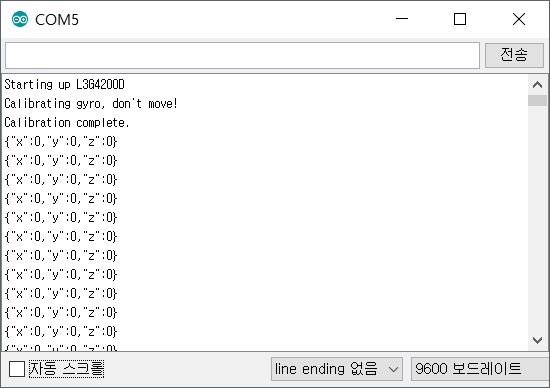
아두이노 시리얼 모니터창에서 반드시 보드레이트(Baudate)를 9600 으로 수정 해야 한다. 그렇지
않으면 시리얼 모니터 창에 아무런 데이터가 표시되지 않거나 잘못된 데이터가 표시될 것이다. 프로세싱 데이터를 처리하기 위한
데이터 이므로 데이터를 바로 판독하기는 어렵다. 데이터가 올바르게 표시되는것을 확인 하였다면 프로세싱에서 동일한 시리얼포트를
사용해야 하기 때문에 아두이노 시리얼 모니텅 창을 닫도록 하자.
3.4
프로세싱 코드
프로세싱 코드에서 한가지 주의 해야할 사항은 시리얼 포트를 각자의 환경에 맞추어서 수정을 해주어야 한다는 것이다.
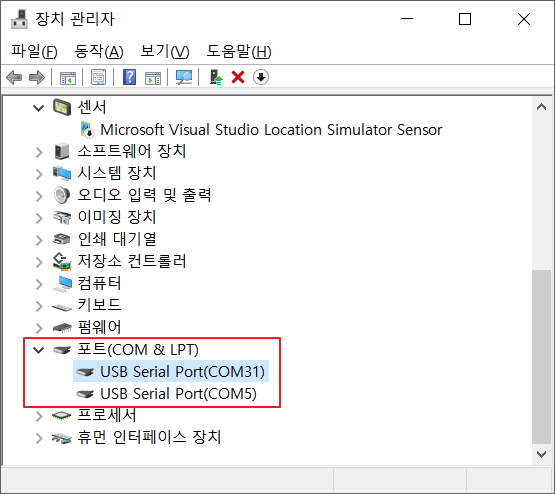
아래 프로세싱 코드에서 "[0]" 의 0이라는 숫자는 장치관리자에서 COM포트의 번호가 아니라 포트의 순서라는것에 주의 해야 한다.
위의 장치관리자 화면에서 예를 든다면 다음과 같다.
Serial.list()[0]; // --> COM31
Serial.list()[1]; // --> COM5

프로세싱 코드를 실행할때 테스트하는 PC의 COM 포트 상태에 따라서 "Serial.list()[0]" 의 숫자를 바꾸어 주어야 한다.